LAB 5
Open-Loop Control
Lab 5 is where we finally assembled the complete robot. This involved wiring the motor drivers to the existing Artemis and the sensor circuit to the motor drivers and the motors on the RC stunt car. By the end of this lab, we had a battery-powered robot with open-loop control to execute a series of moves.
Wiring the Motor Drivers
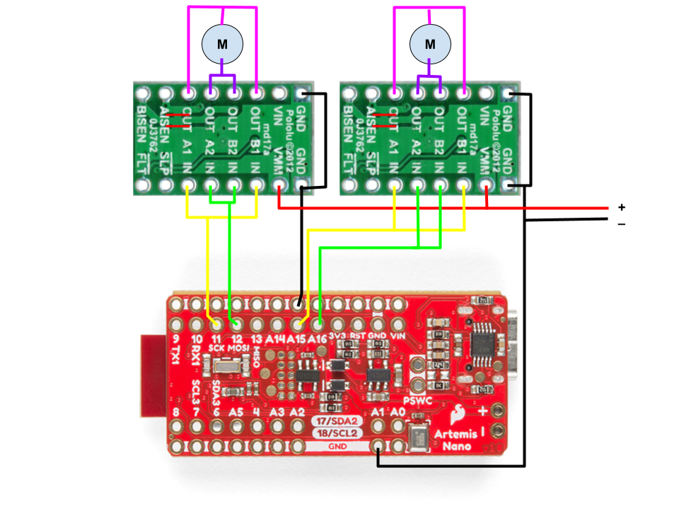
The first part of the lab involved connecting the two motor drivers to the Artemis board. Since we need to control the speed of the motors, the appropriate outputs are the PWM pins. The motor driver is an H-Bridge IC that allows PWM control in both directions using two inputs for each channel. Each motor driver has two channels, and in order to increase the current output to the motor, we couple the two channels on two drivers to run two motors (this allows the motors to run fast). The Artemis board consists of several PWM pins, and I used pins 11, 12, for motor A, and 15, 16 for motor B. The motor and Artemis grounds are shorted to create a common ground, but the voltage supply for both are different, which isolates Artemis from power fluctuations in the motors. I started with connecting one motor, testing it, and then moving to the second motor.
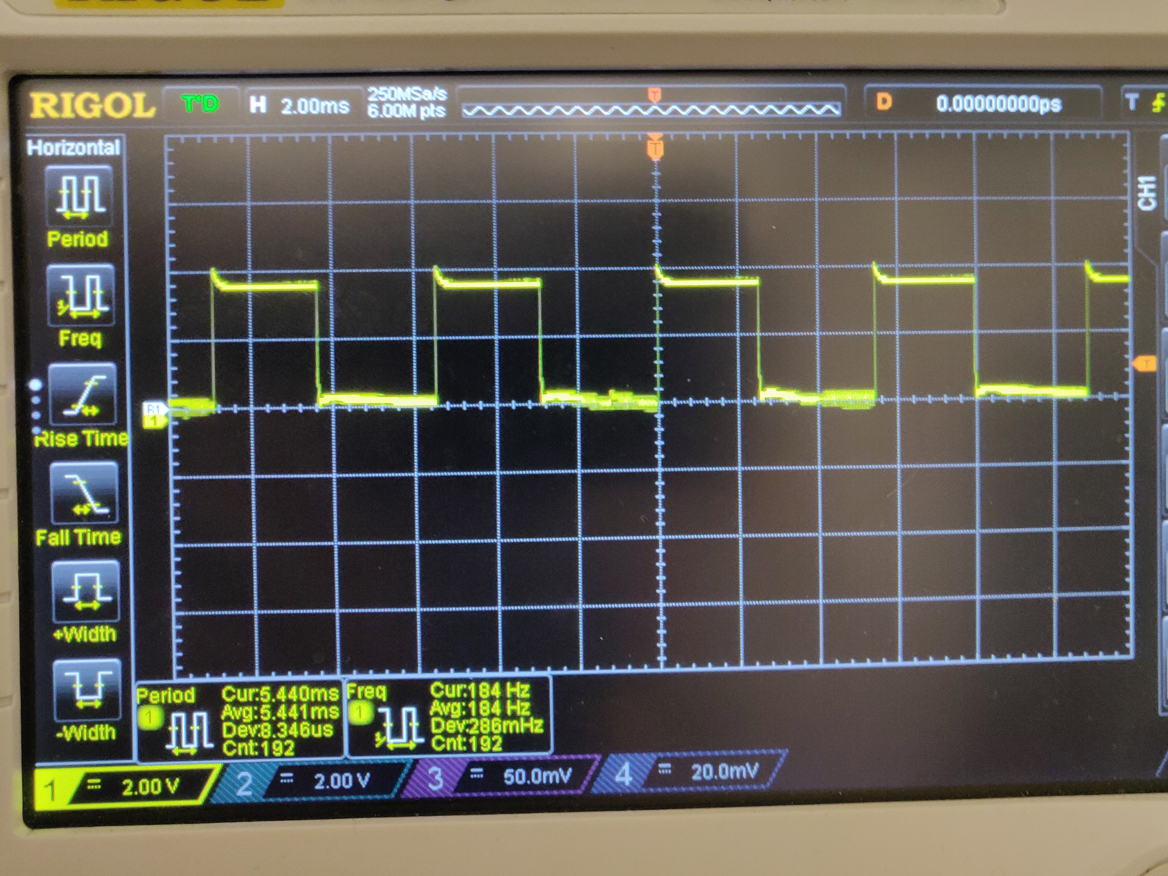
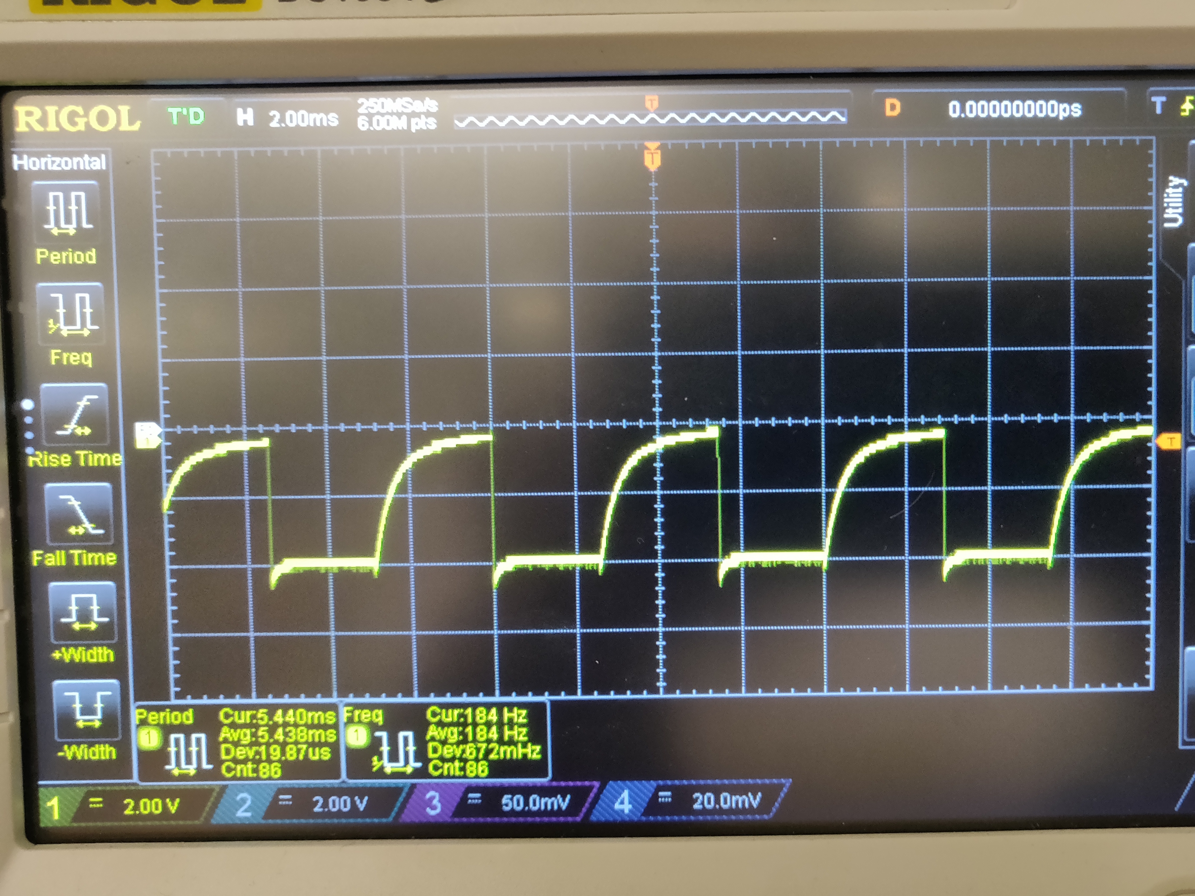
Once a motor driver was connected to Artemis, I tested it using a basic PWM code on the Artemis as shown below. The analogWrite() Arduino function takes an input between 0-255 and maps it to a PWM duty cycle (0% to 100%) to run motors on different speeds. For initial testing, we used a power supply for the motor power, and connected the motor driver output to an oscilloscope channel to view the PWM output. The oscilloscope plot for the motor driver outputs in both directions, running at an analog value of 100 are shown below (power supply voltage of 3.7 V). I repeated this process with the second motor driver after this.
// Code for outputting PWM from the Artemis to control the motor driver to run in one direction

int motorA_in1 = 11;
int motorA_in2 = 12;

void setup() {
    pinMode(motorA_in1, OUTPUT);
    pinMode(motorA_in2, OUTPUT);
}

void loop() {
    int curr_speed = 100;

    analogWrite(motorA_in1, curr_speed);
    analogWrite(motorA_in2, 0);
}
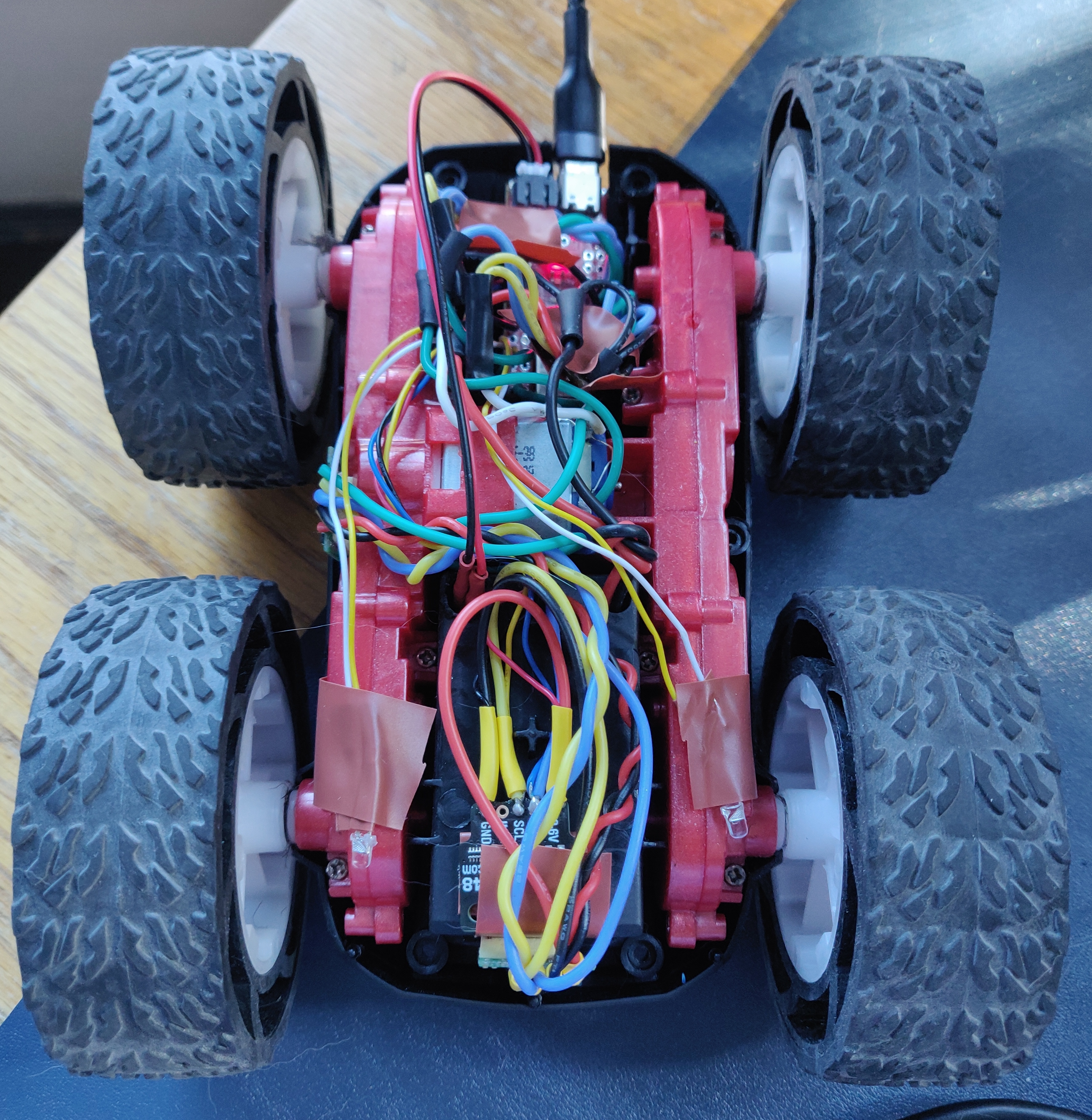
Assembling the Robot
Once the motor driver circuit was complete on the Artemis side, we disassembled the car and placed the circuit inside. The motor driver outputs were coupled and connected to the two motors in the chassis, while the motor power supply and ground are connected to the two battery wires in the car. Given the tight space on the car, it was important to carefully consider the placement of all the components (Artemis, motor drivers, IMU, TOF sensors) and their connecting wires inside the car. I assembled the circuit onto the car and placed all the components as shown below. Given the slightly longer wires, it would be a tight fit if I place the top cover of the car, and it would also stress the wire joints, so I need to be extremely careful. To make the robot battery-powered, we use the 650 mAh battery to power the Artemis, and the 850 mAh battery for the motors. These were both housed in the battery compartment on the other side of the car. Using two batteries also allowed the robot to run for a longer duration.
After hooking up everything in the robot, I tested my previous basic code to see if the motor was running and the wheels were rotating. The videos below show both sides of the wheels rotate in both directions while the robot is powered by the two batteries.
Demonstration
Finally, the robot was completely assembled and could be run on the floor. I ran the robot with a few different PWM values and found the lower limit to be 40, below which the duty cycle wasn’t high enough to move the robot from its position. With a few attempts, I checked if both the motors were calibrated to the same speed so that the robot can move in a straight line. In the case of my robot, both motors running at analog value of 100 resulted in a completely straight line motion as shown below (with the sample code used to perform the test).
void loop() {
    int curr_speed = 100;
    // Delayed start to allow time for placing the robot
    delay(5000);

    // Run forward for 2 seconds
    motor_fwd(motorA_in1, motorA_in2, curr_speed);
    motor_fwd(motorB_in1, motorB_in2, curr_speed);

    delay(2000);

    motor_stop(motorA_in1, motorA_in2);
    motor_stop(motorB_in1, motorB_in2);

    // Busy wait
    while (1);
}

void motor_fwd(int in1, int in2, int spd)
{
    analogWrite(in1, spd);
    analogWrite(in2, 0);
}

void motor_back(int in1, int in2, int spd)
{
    analogWrite(in1, 0);
    analogWrite(in2, spd);
}

void motor_stop(int in1, int in2)
{
    analogWrite(in1, 0);
    analogWrite(in2, 0);
}
After running the robot in a straight line, I performed open loop control on the robot, running it over a series of forward movements and turns as described in the code and video below.
void loop() {
    int curr_speed = 100;
    delay(5000);

    // Move forward
    motor_fwd(motorA_in1, motorA_in2, curr_speed);
    motor_fwd(motorB_in1, motorB_in2, curr_speed);

    delay(1000);

    motor_stop(motorA_in1, motorA_in2);
    motor_stop(motorB_in1, motorB_in2);

    delay(500);

    // Turn left
    motor_fwd(motorA_in1, motorA_in2, curr_speed);
    motor_back(motorB_in1, motorB_in2, curr_speed);

    delay(1000);

    // Move forward
    motor_fwd(motorA_in1, motorA_in2, curr_speed);
    motor_fwd(motorB_in1, motorB_in2, curr_speed);

    delay(1000);

    motor_stop(motorA_in1, motorA_in2);
    motor_stop(motorB_in1, motorB_in2);

    // Busy wait
    while (1);
}