LAB 6
Closed-Loop Control (PID)
In this lab, we programmed the robot to perform a stunt with the help of closed-loop control. This was an exciting lab because it was the first software-focused lab of this course where we programmed the Proportional, Integral, Derivative (PID) controller. Lab 6 is the first part in the series of labs 6-8, where we used controllers and sensor fusion to finally perform complete stunts on the robot.
This lab involved getting a basic behavior working for our choice of one of the three given tasks. I chose to perform Task B in which the robot goes forward, turns and drifts around to a complete 180° flip, and moves straight back. I collaborated on this lab with Aryaa Pai (avp34) and Aparajito Saha (as2537) to discuss implementation and debugging.
Prelab
In order to help with the tuning of PID and debugging during the lab, we needed to complete a prelab to set up a codebase for the Artemis side and the python side. This involved integrating various code elements from previous labs, like Bluetooth, IMU, motor PWM.
I adopted the Bluetooth framework directly from Lab 2 with the necessary modifications for this lab’s use case. This meant that on the computer side, I have a simple Jupyter notebook with different cells to connect to the Artemis and send different commands. On the Artemis, a command handler was called whenever a new command was received with RX_STRING characteristic, and the commands were handled through a switch-case construct. For this lab, however, I replaced all the Bluetooth commands to perform different actions and also added some to assist with tuning and debugging. The code snippets below show all the commands added and the implementation in Jupyter notebook and Artemis.
// lab6.ino
// Segment of code from bluetooth command handler on Artemis

void handle_command() {
    // Set the command string from the characteristic value
    robot_cmd.set_cmd_string(rx_characteristic_string.value(),
                                rx_characteristic_string.valueLength());

    bool success;
    int cmd_type = -1;

    success = robot_cmd.get_command_type(cmd_type);

    // Check if the last tokenization was successful and return if failed
    if (!success) {
        return;
    }

    // Handle the command type accordingly
    switch (cmd_type) {
        /*
        * Move the robot forward for given number of milliseconds
        */
        case MOVE_FORWARD:
            int spd_;

            // Extract the next value from the command string as an integer
            success = robot_cmd.get_next_value(spd_);
            if (!success)
                return;

            Serial.print("[COMMAND] Move forward by: ");
            Serial.println(spd_);

            // Move the robot for 1 second
            robot.move_forward(spd_);
            delay(1000);
            robot.slow_stop();

            break;

// ...
// More cases for different commands
# cmd_types.py
# Bluetooth command types
class CMD(Enum):
STOP = 0 # ble.send_command(CMD.STOP, "") -- Stops the robot
MOVE_FORWARD = 1 # ble.send_command(CMD.MOVE_FORWARD, "100") -- Move forward for 1s with speed 100
MOVE_BACKWARD = 2 # ble.send_command(CMD.MOVE_BACKWARD, "100") -- Move backward for 1s with speed 100
TURN_RIGHT = 3 # ble.send_command(CMD.TURN_RIGHT, "150") -- Turn right for 1s with speed 150
TURN_LEFT = 4 # ble.send_command(CMD.TURN_LEFT, "150") -- Turn left for 1s with speed 150
PERFORM = 5 # ble.send_command(CMD.PERFORM, "") -- Perform task B
GET_DATA = 6 # ble.send_command(CMD.GET_DATA, "0") -- Get data from Artemis, 0/1 specify which data
PID_GAINS = 7 # ble.send_command(CMD.PID_GAINS, "0.1|0.0|1.0") -- Set PID gains kp, ki, kd
SET_SPEEDS = 8 # ble.send_command(CMD.SET_SPEEDS, "120|160") -- Set minimum and maximum speed for the robot
SET_POINT = 9 # ble.send_command(CMD.SET_POINT, "180.0") -- Setpoint for PID# lab6.ipynb
# Bluetooth setup on Jupyter notebook to send commands and get data from Artemis
ble = get_ble_controller()
ble.connect()
ble.send_command(CMD.PERFORM, "")
def float_receive_cb(uuid, float_value):
global debug_data
global data_length
global flag
if flag == 0:
data_length = int(ble.bytearray_to_float(float_value))
print(f'Expected size: {data_length}')
flag = 1
else:
debug_data.append(ble.bytearray_to_float(float_value))
flag = flag + 1
async def get_data(code):
global debug_data
debug_data = []
ble.start_notify(ble.uuid['RX_FLOAT'], float_receive_cb)
ble.send_command(CMD.GET_DATA, code)
await asyncio.sleep(120)
ble.stop_notify(ble.uuid['RX_FLOAT'])
asyncio.run(get_data("0"))To control the motors on the robot with varying PWM for different speeds, I created a handler class RobotControl shown below. This consisted of all the necessary information about the hardware connections and contained functions to move the robot forward/backward, right/left, and stop with a given speed.
// RobotControl.h

/*
* Class to control the robot by manipulating the motors
*/
class RobotControl
{
    public:
    /**
    * Default constructor
    * Sets up all the motor driver pins as output
    */
    RobotControl()  {}

    /**
    * Function to move the robot forward
    *
    * @param speed integer variable to specify the speed of motor movement (PWM duty cycle)
    */
    void move_forward(int speed)  {}

    /**
    * Function to move the robot backward
    *
    * @param speed integer variable to specify the speed of motor movement (PWM duty cycle)
    */
    void move_backward(int speed)  {}

    /**
    * Function to turn the robot right
    *
    * @param speed integer variable to specify the speed of motor movement (PWM duty cycle)
    */
    void turn_right(int speed)  {}

    /**
    * Function to turn the robot left
    *
    * @param speed integer variable to specify the speed of motor movement (PWM duty cycle)
    */
    void turn_left(int speed)  {}

    /**
    * Function to stop the robot instantly
    */
    void fast_stop()  {}

    /**
    * Function to stop the robot slowly
    */
    void slow_stop()  {}
};
Similarly, to interact with the IMU sensor using I2C, I created a IMU class to encapsulate the setup of the sensor and obtain its readings to measure the yaw angle (for task B). I used the gyroscope integral method to calculate the yaw and found it to have a linear error in the observed angles, which I fixed with a two-point calibration method.
// IMU.h

/*
* Class to handle communication with the IMU sensor
*/
class IMU
{
    private:
    // Member variables for angles along X, Y, Z
    float angle_X;
    float angle_Y;
    float angle_Z;

    // Object for sensor
    ICM_20948_I2C sensor;

    // Variable to store the previous time readings were updated
    int last_time;

    public:
    /**
    * Default constructor
    * Initializes all angles to 0.0
    */
    IMU()
    {
        angle_X = 0.0;
        angle_Y = 0.0;
        angle_Z = 0.0;

        last_time = millis();
    }

    /**
    * Setup and initialize the sensor
    */
    void setup()  {
        // Initialize the sensor
        bool initialized = false;
        while (!initialized)
        {
            sensor.begin(Wire, AD0_VAL);

            Serial.print(F("[IMU] Initialization of the sensor returned: "));
            Serial.println(sensor.statusString());
            if (sensor.status != ICM_20948_Stat_Ok)
            {
                delay(500);
            }
            else
            {
                initialized = true;
            }

            // Set full-scale settings for gyroscope
            ICM_20948_fss_t FSS;
            FSS.g = dps1000;

            sensor.setFullScale(ICM_20948_Internal_Gyr, FSS);
        }
    }

    /**
    * Update the sensor readings
    *
    * @return 1 if successful else 0
    */
    int update_sensor()  {
        int status = 0;

        if (sensor.dataReady())
        {
            int dt = millis() - last_time;
            sensor.getAGMT();

            // Update angle Z (yaw)
            angle_Z = angle_Z - sensor.gyrZ() * dt * 0.001;

            last_time = millis();

            status = 1;
            return status;
        }
        else
            return status;
    }

    /**
    * Return latest yaw value
    *
    * @return angle_Z
    */
    inline float get_yaw()  {
        // Two-point calibration on yaw (angle_Z)
        float curr_angle_Z = ((angle_Z - YAW_RAW_LOW) * (YAW_REF_HIGH - YAW_REF_LOW) /
            (YAW_RAW_HIGH - YAW_RAW_LOW)) + YAW_REF_LOW;

        return curr_angle_Z;
    }

    /**
    * Reset the sensor angles
    */
    inline void reset_sensor() {
        angle_Z = 0.0;
    }

};
Finally, I also created a static array data structure to efficiently store any data (yaw, error, speeds, etc.) and send it to the computer later for logging.
PID
The PID controller is a common closed-loop control system used in robotics. PID provides the required output to reach a specified setpoint, based on the feedback obtained using a sensor to calculate the error. In the case of task B, the output of the system would be the PWM duty cycle with which the robot turns, while the setpoint and the feedback would be of the yaw angle measured using the gyroscope in the IMU.
As the name suggests, PID includes proportional, integral, and derivative terms of the measured error, determined by constants kp, ki, kd. The sum of these terms produces the next output speed of the motors. Determined experimentally, the robot has a deadband speed below which it doesn’t move on the ground (which changes as the batteries get depleted). For this lab, we also want the robot to move slowly to ensure stability and thus put an upper limit on the speed from the controller. The final motor speed from these limits and the PID output to also account for turning in different directions has been shown below.
// lab6.ino
//  turnPID() function

int pid = (int)p + (int)d + (int)i;

if (pid > 0)
{
    int speed = min_speed + pid;
    if (speed > max_speed) speed = max_speed;

    robot.turn_right(speed);
}
else
{
    int speed = min_speed - pid;
    if (speed > max_speed) speed = max_speed;

    robot.turn_left(speed);
}
I started implementing PID on the robot with the P term. With a low value of proportional constant (below 0.1), I found that while the robot turned, it stops at an angle significantly below the target. This steady-state error is expected because the robot with a low P term is unable to overcome the deadband speed. At a high constant, we see that the robot turns and overshoots the target angle, only to turn back and eventually start oscillating around the target with a low amplitude.
// lab6.ino
// turnPID() Function
// Code for P term

float error = target_yaw - yaw_curr;

// Proportional term
float p = (kp * error);
After getting a suitable range of constants for the P term, I added the derivative term. As expected, the D term reduced the speed of the robot even quicker as it approached the target angle, thus reducing the overshoot. Even without a low-pass filter, the derivative gave stable enough values to be added to the controller.
// lab6.ino
// turnPID() Function
// Code for D term

int dt = millis() - last_time;

float error = target_yaw - yaw_curr;

// Derivative term
float d = kd * (error - last_error) / (float) dt;
last_error = error;
last_time = millis();
After carefully selecting the proportional and derivative gains, I was able to produce the desired response of task B. I tried to also add the integral term, but I was unable to properly account for the extremely high accumulation of the error sum leading to a high output speed. For the complete sequence, I implemented a timed forward movement, followed by the 180° turn and another timed forward movement. In order to detect that the robot had reached its desired angle, I counted its oscillations through the change of sign of error.
// lab6.ino
// Case PERFORM in command handler

/*
* Perform the task
*/
case PERFORM:
    Serial.println("[COMMAND] Perform");

    // Reset the data structures for yaw and speed
    yaw_data.reset_data();
    speed_data.reset_data();

    // Reset the IMU sensor
    imu_sensor.reset_sensor();

    // Move the robot forward for 1 sec
    start_time = millis();
    robot.move_forward(180);
    // Variable for running average yaw
    while(imu_sensor.update_sensor() == 0) delay(20);
    yaw_avg = imu_sensor.get_yaw();

    while (millis() < start_time + 1000)
    {
        if(imu_sensor.update_sensor())
            yaw_data.add_data(imu_sensor.get_yaw());
        yaw_avg = (yaw_avg + imu_sensor.get_yaw()) / 2;
    }
    robot.fast_stop();
    delay(100);


    // Turn 180 degree
    target_yaw = yaw_avg + setpoint;
    last_error = setpoint;
    osc_count = 0;
    Serial.print("Target yaw: ");
    Serial.println(target_yaw);

    start_time = millis();
    last_time = millis();
    done = 0;
    while (done == 0 && (millis() - start_time < 2000))
    {
        done = turnPID(target_yaw);
    }
    robot.fast_stop();
    delay(100);

    // Move the robot back for 1 sec
    start_time = millis();
    robot.move_forward(180);
    while (millis() < start_time + 1000)
    {
        if(imu_sensor.update_sensor())
            yaw_data.add_data(imu_sensor.get_yaw());
        yaw_avg = (yaw_avg + imu_sensor.get_yaw()) / 2;
    }
    robot.fast_stop();

    break;
Demonstration and Results
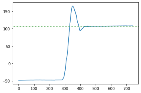
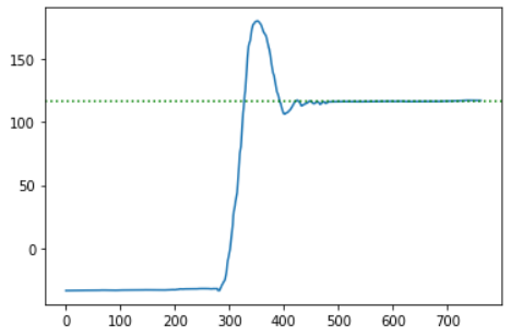
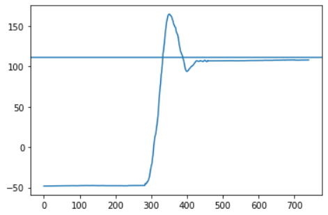
The videos included below show the three trials performed on the robot with the discussed implementation of PID control. The robot seems to be performing the task very well in all the three cases, where it moves forward, turns around quickly, and comes back almost to the same spot. After each video, a plot shows the measured gyroscope angle as the robot moves, and we can see how the angle is stable in the beginning (during the forward motion), then changes to the setpoint while turning, and quickly stabilizes to the new angle while coming back. The PID control parameters and other variables were set to the values shown below.
While tuning the controller and conducting multiple trials, I found that in order to achieve a complete 180° flip, the setpoint needs to be around 150°. This offset consistently provided the expected result, so I conducted the final trials this offset setpoint. Another observation is that even though the robot turns around completely, it doesn’t retrace its path back to the starting position and instead follows a parallel path to the right. This could be because the robot is not turning on the spot but instead taking a bigger turn radius. I suspect that this can be fixed by calibrating the two motors while turning such that they move with the exact same speed, and I plan to test and fix this before Lab 8.